Any telecommunication system that uses optical fiber as transmission media consists of optical transmitter, optical transmission line, optical receiver, as shown in picture 3-1, including EPON system. It’s important to understand the category and working principle of optical transmitter and optical receiver. This section introduces the optical transmitter, and optical receiver will be introduced in next section.

Picture 3-1 component of optical fiber transmission system
The key of optical transmitter is producing laser or fluorescent light sources, which is an important composing part of optical telecommunication system. Presently, light source for optical fiber telecommunication system includes Laser Diode (LD) and Light Emitting Diode (LED). LD emits interference lights and LED emits non-interference lights. They are both small in volume, weight and power consumption. Laser Diode features high modulation rate and high coupling efficiency with optical fibre. And is suitable for large capacity, long distance transmission system. LED has good output characteristic curve, long life span and low cost and is suitable for small capacity, short distance transmission system.
1. Working principle of Laser Diode
Laser Diode is actually a Stimulated Emission Optical Oscillator. Its working principle is a luminescence process of stimulated radiation. Electrons of semiconductor substance glow between band transitions. Cleaved surface of semiconductor crystal is used to form two parallel reflectors which forms a resonant cavity that oscillate and rebound lights and cause amplification of optical radiation and finally emit laser.
Semiconductor laser is a coherent radiation source. It must include 3 basic conditions for generating laser.
2. Working principle of Light Emitting Diode
In telecommunication, LED can be understand as a converter that convert electric power into optical power. LED has 3-layer structure of N-P-P. The middle is an active layer consists of GaAs type P semiconductor. The bandgap width of this middle layer is small. Besides the middle are type N and type P semiconductor made of AlGaAs. Compared with the active layer, they have wider bandgap width. The contact surface of two semiconductor of different bandgap width is called heterojunction. Active layer P and left layer N forms heterojunction P-N, and active layer P and right layer P forms heterojunction P-P. This structure is also call double Heterojunction N-P-P structure, short as DH structure. When positive bias voltage is added on the structure, electrons move from layer N to middle layer P. and under the influence of heterojunction P-P, the electrons stop at the active layer P, which compound with holes. In the process of compounding, electrons emit photon, whose energy follows below formula:
hγ=E1-E2=Eg
Note: h is the Planck constant, γ is the frequency of light wave, E1 stands for the energy of electrons in active layer,
E2 stands for the energy of electrons after they compound with holes. Eg’s value is related to the material of each layer and its component. When making LED, these raw material and component must be adjusted to generate lights of right wavelength.
3. Characteristics of LD and LED.
1) Characteristics of LD
A. Spectral characteristics
The spectrum of LD changes as excitation current changes. When excitation current is smaller than threshold current, LD emit florescent light and the spectrum is very wide. When excitation current is larger than threshold current, the spectrum become narrow, the spectrum center intensity increase sharply and emit laser. Laser Diode of different structure may emit laser that presents one spectrum line and it’s called single longitudinal mode laser. If it presents more close spectrum lines, it’s called multiple longitudinal mode laser.
B. Threshold value characteristics
Threshold value means the threshold current of the laser diode. To make optical telecommunication system work stable and reliable, the smaller the threshold current the better. The graph of relations between the working current of LD and its output power is the output characteristics graph curve of the LD, which is an important parameter for LD.
C. Temperature characteristics
Some variation occurs to the threshold current of Laser Diode as temperature changes. Temperature characteristics refers to the fact that the threshold current and output power change as temperature changes. To guarantee the stability and reliability of the optical telecommunication system, automatic temperature control circuit is used to stabilize the threshold current and output power of the Laser Diode.
D. Conversion rate
Conversion rate of LD refers to the ratio between optical output power the the input electric power.
2) Characteristics of LED
A. Wider Spectrum
LED is self-radiating so its spectrum is wider than LD’s, which is not conducive for high speed signal transmission.
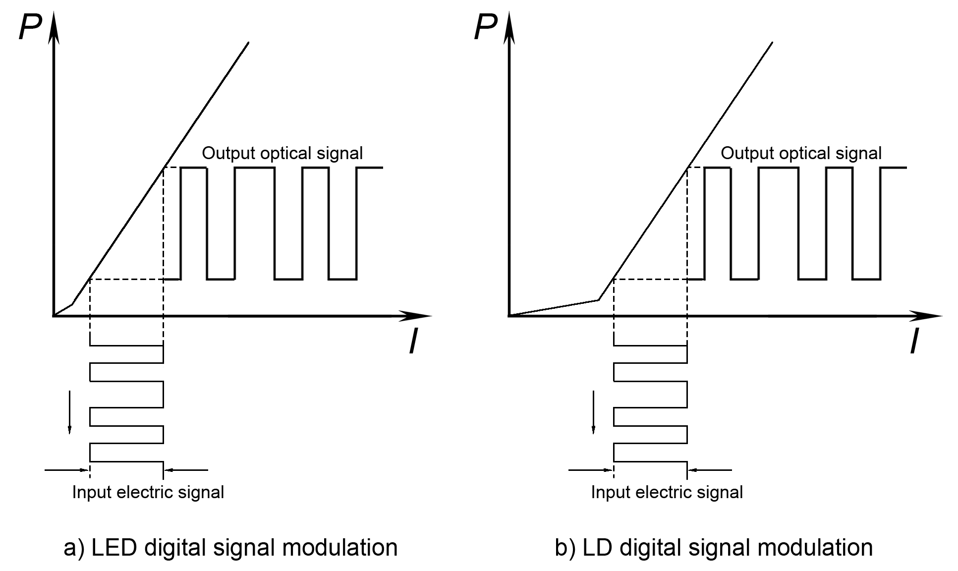
B. Good P-I curve. LED has no threshold value, its output power features a approximately linear increase as input current increase, so in signal modulation, its dynamic range is larger and Signal distortion is smaller.
C. LED’s coupling efficiency with optical fibre is lower, because LED lights have large divergence angle. That’s why LED is used for short distance transmission.
D. Good temperature characteristics. LED has not threshold value, so it has better temperature characteristics and need no temperature control system.
4. Modulation of Light Source
Modulation of light source is the process of imposing electric signal onto light wave. It’s generally completed in ways: direct modulation and indirect modulation. Important parameters of modulated light source include power, amplitude, frequency and phase.
1) Direct modulation
In direct modulation, electric signals carrying information are input into LD or LED to emit lights that carries required information. It’s also called internal modulation, because it’s done inside light generator. Direct modulation further includes analog modulation and digital modulation.
3) Indirect modulation
Indirect modulation is done on the output route of lights. Based on photo-electric and acoustic-electric effect, light transmission in crystal can be changed when the voltage imposed on it changed. This was the principle is used in indirect modulation of light wave.
The widely applied is direct modulation of light intensity. Below is the brief introduction of direct modulation of light.
When optical fiber system is used to transmit digital signals composed of a series of “0” and “1”, the LED modulator’s working principle is shown in picture a); the LD modulator’s working principle is shown in picture b).

1. Component and main technical parameter of optical transmitter.
1) Component of optical transmitter
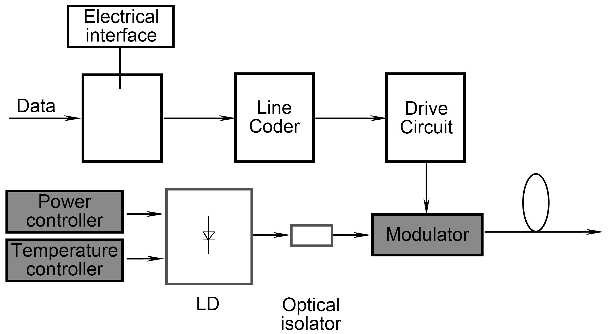
Optical transmitter is a key equipment for optical transmission system. It modulates light under the guide of the input electric signal, so that electric signals are converted into light signals. Optical transmitter can output continuous, stable and reliable light signal. The component of modulator is composed of light source, line coder, drive circuit, modulator etc., as shown in below picture:

Line coder: digital signal is bipolar code that is easy for electric cables, while optical source can only emit unipolar code. So line code is needed to transform electrical bipolar code in to unipolar code.
Drive circuit: drive the modulator following the output signal from the line coder, and ensure that the output optical signal accurately correspond to the the input electric signal.
Modulator: modulate light signal.
Power controller: ensure that LD output constant optical power.
Temperature controller: ensure that all LD components work at constant temperature, so that LD works stably.
Optical isolator: Prevent the reflection of laser emitted by LD, and guarantee the unidirectional transmission of lights.
1) Key parameters of optical transmitter
Optical transmitters’ performance is usually measured by testing modulated the light signals they emit. For example, optical power, signal eye diagram,Extinction Ratio, Data-dependent jitter, rise time / fall time, width of spectrum, central wavelength, Side-Mode Suppression Ratio. All these parameters must cater to the standard requirement of the interface. Below is the introduction of the main parameters.
A. Eye diagram. Eye diagram refers to the image formed when light signals overlay in the optical time domain. It’s called eye diagram, because it looks like an eye.
B. Data-dependent jitter. Data-dependent jitter is caused by the intersymbol interference that occurs when data travels through a signal path with limited bandwidth.
C. Rise time/fall time. Rise time is the time the signal takes to go from 10% or 20% to 90% or 80% of the altitude. Fall time is the time it takes to go from 80% or 90% to 10% or 20% of the altitude.
D. Extinction Ratio. Extinction Ratios is the ratios between the average optical power for “0” code and the average optical power for “1” code. A ideal modulated light source has no optical output, which otherwise is the noise for the system.
E. Width of spectrum. Spectrum width is the spectral width corresponding to spectral line’s width in space(line dispersion)
F. Side-Mode Suppression Ratio. SMSR is the minimum value of the the ratio between the average optical power on the main mode and the most significant optical power on the side mode under the worst reflection and full modulation.
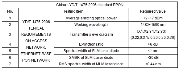
Below is the introduction of specific requirement on optical transmitter, using 1000Base-PX20-D for OLT equipment.
Testing items on Transmitter for PON interface on OLT equipment.
